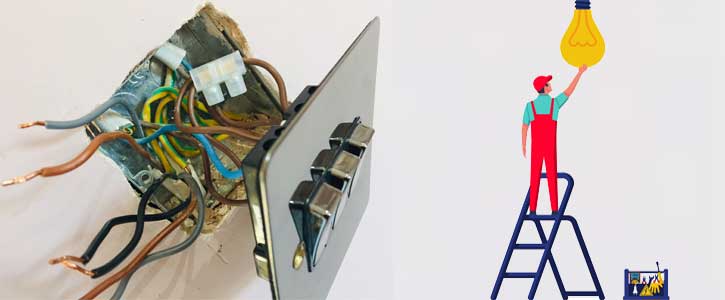
Wiring a Light Switch
This FAQ has been produced to explain the different types of light switches, circuits and terminologies that are used in modern day lighting installations. Ranging from simple one way switches to more advanced keypads that are used in home automation systems such as Lutron.
Any electrical wiring should be done by a qualified electrician. We are not electricians and have taken all the diagrams from the instructions that are supplied with the products we sell. Basic safety procedures should always be followed such as switching off the mains supply before commencing any work. The maximum current rating should also be adhered to; this is usually 6 to 10 amps per switch for on/off switches and for dimmer switches its 250W or 400W. LEDs often need to be de-rated, for example the Varilight V-Pro is rated a 120W for LED and 400W for incandescent with a maximum of 10 LEDs. These ratings differ with 1 gang, 2 gang and 3 gang versions.
If you’re attempting to wire anything more complicated like upgrading a 4 gang light switch to a 4 gang dimmer switch it may be worth taking a quick photo first just in-case you get muddled up with the wires and need to revert back.
Wiring a One Way Switch
A one way light switch has two terminals which is a common marked as COM or C. The common is for the live wire that supplies the input voltage to the switch. The other terminal is marked as L1 and is the output to the light fixture.
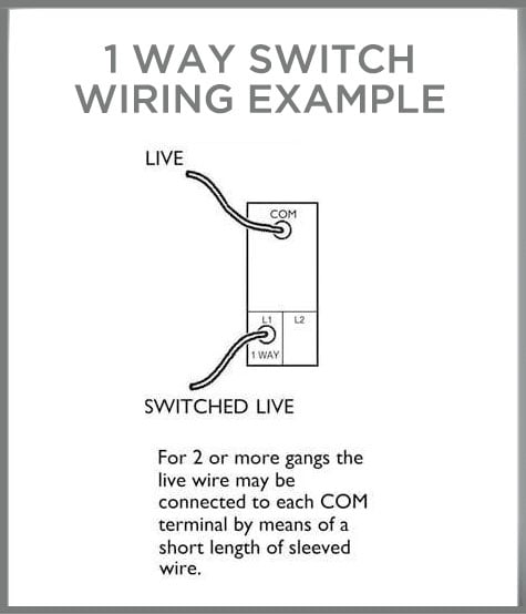
When you’re wiring decorative light switches such as chrome or stainless steel etc, you’ll find that the switch will also have an L2 terminal which means it’s a two way switch. If you’re circuit is only one way, you can ignore this terminal and it will still work. This is because two way switches can also be used on one way circuits. Manufacturers don’t make decorative one way switches.
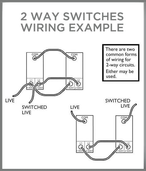
Wiring a Two Way Switch
The more popular light switch with two way switching, which means you can switch the same light fixture from two switches that are located in different sides of a room. Two way switches have a COM terminal as well as L1 and L2 terminals.
- When L1 is off L2 would be on.
- When L1 is on L2 would be off.
There are two wiring options for this:
More advanced dimmer switches like Varilight Eclique (now called V-Pro Multi-Point Touch) and Lightwave have an S terminal instead. The S terminal can only be linked up to a corresponding slave and won't work with an ordinary two way switch. Here is a wiring example of a Lightwave RF Gen1 dimmer switch shown from behind:

Intermediate Switch Wiring
Intermediate switching is similar to two way but allows a third switch to be integrated. An example of this would be having one switch at the bottom of a staircase, one at the top and one in the middle. It’s not known as three way switching because you can also add more switches for four way switching or more.
Intermediate switches have terminals marked L1, L2, L3 and L4. Check out the diagram below that shows how to way a three way switch:

Two Way Dimming
Two way dimming allows you to dim a light fixture from two locations. You can’t use ordinary rotary dimmer switches to do this because you could potentially dim the light down to 10% with one dimmer, then walk over to the other dimmer and attempt to dim the light to below 0%. Or vice-versa you could be attempting to brighten the light above 100%. This would cause major instability on the circuit, like the time when the ghost busters crossed the beams!
You can have a dimmer switch and an on/off switch on the same. The dimmer will do the dimming and the two way switch will be able to switch it on and off. If you've dimmed the lights to 50% the switch will keep switching it and off at that level until you dim it again.
Up until fairly recently two way dimming was quite expensive, it could be done using Lutron Rania until they got discontinued. With the arrival of Varilight V-Pro multi-point dimmers (formally Eclique) and Lightwave Smart switches, this is now easy to do and doesn't cost too much. Varilight requires a combination of master and slave dimmers for it to work. While the Lightwave Smart series dimmers can be programmed via their App to perform 2 way or even 3 way dimming.
Wireless Switches
Wireless switches usually require an additional receiver or relay for them to work. The receiver is positioned in the ceiling void near to the lights. It receives an RF (Radio Frequency) signal from the switch to tell the receiver what to do. If you've already got wires in place you can still use a wireless switch by terminating the wires.
Brands like Rako and Lutron have their own wireless systems. Lightwave discontinued their Gen1, Connect Series but now have a great new range of wire-free switches which are part of the Smart Series.You can either use them with a relay or with a smart switch. They can be stuck or positioned to any surface and look like an ordinary switch but have considerably more functions.
Wireless switches used to be battery powered, Ener-J have taken this a step further with their kinetic switches. Using the energy generated from pressing the switch, which is enough to send the signal to the receiver. The receiver then switches the lights and are available in dimmable or non dimmable versions, as well as a Wi-Fi version for smart phone control. They can either be screwed or stuck to a surface and have IP65 rated versions which are ideal for bathrooms.
Smart Phone Dimming
If you want to control your lights from a smart phone, the easiest and most cost effective way of doing this is with Lightwave. All you need is a master dimmer switch, the Lightwave RF Wi-Fi hub and the App which is free to download. The new Smart Series dims LEDs effortlessly and provides timer and scene setting functions. You can also control smart power sockets, heating controls and other Lightwave add-ons.
Lutron QS Keypad Wiring
One of the main advantages of using a home automation system over traditional dimmer switches is that you can replace those big clunky looking double plate, three and four gang dimmer switches with trendy looking keypads. Lutron keypads have up to 10 buttons as well as dim up and dim down. The buttons can be programmed to create lighting scenes of your choosing. Here is an example of an engraved 5 button Lutron SeeTouch keypad in satin nickel with black buttons.
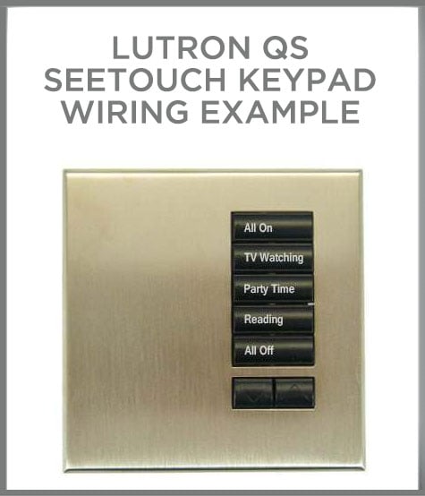
Once you’ve decided on the function of each scene you can get the buttons engraved by completing a form and sending back to Lutron, this is included in the price of the keypad. You could either have something simple like Scene 1, Scene 2 etc or try something more adventurous like 'All On', 'TV Watching', 'Party Time', 'Reading' and 'All Off' like in my example. A scene can be a mixture of multiple lighting circuits that are all set to different dimming levels. 'TV Watching' could dim your main LED downlights down to 10%, your wall lights down to 30%, your cove LED strip lights down to 50% and even switch a table lamp on, all at the touch of one button.
If you’re considering installing a full home automation such as Lutron Grafik Eye QS or Energi Savr Node (known as ESN), the corresponding keypads which are known as SeeTouch need to be wired totally differently to any of the traditional switches that we’ve mentioned. Firstly they require a 24V DC supply which can be taken directly from the Grafik Eye or ESN. The keypads can also control electronic blinds which are also available from Lutron.
Using the recommended Lutron control cable which has two pairs of cables, one pair is for power and the other pair is for signal. Additional keypads and other components can then be linked from one to the other using the QS Link terminal. You can even link a Grafik Eye QS to an Energi Savr Node and have them both on the same system.
The Lutron Grafik Eye is now discontinued as it was too overpriced to keep up with other up and coming smart lighting brands.
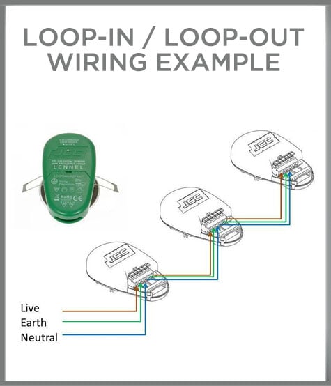
Lighting Circuits – Loop In, Loop Out
The favoured way of wiring recessed downlights is using the loop in, loop out method. This is a form of parallel wiring that has one cable (usually twin and earth 6242Y) containing the live, neutral and earth wires looping in and then out of leach light fitting. This is an alternative to the traditional junction box system, it uses less cable and is faster to complete.
Many downlights have a loop in, loop out terminal block attached to them. For example the Ansell iCage has the largest one which was specifically designed for this type of wiring. A popular feature for downlights is push-fit terminals which also have loop in, loop out terminals. Some have them directly attached to the downlight and some come with wiring connectors. The image below shows the loop-in, loop-out wiring method:
When installing downlights that don’t have their own connection system, many installers create their own by using a Click Flow Connector. With this connector you wire the smaller male connector into the downlight and the corresponding female connector into your loop in, loop out circuit. Then you simply plug the downlight into the circuit and continue the process with the next ones.
Other downlights like the Aurora M Series and Click Ovia Nano are supplied with their own wiring connectors. The male connector is already pre-wired into the downlight so half of the work is already done for you. Another advantage of using Flow Connectors is if the downlight fails you can unplug it and get it replaced yourself without having to get an electrician back in to disconnect it and then reconnect the replacement.
Lighting Circuits – Series Wiring
Series wiring is mainly used with multiple LED lights that are powered from the same LED driver. It is usually used with smaller LED downlights or with LED ground lights that are constant current. The most popular constant current ratings are 350ma or 700ma. This diagram below shows how it's done:

Although many of the LED downlights we offer are constant current, they are each supplied with their own LED driver with is either directly attached to them or trails behind them like an old fashioned halogen and low voltage transformer combination. If you’re wiring a mains supply into each LED driver individually it would be classed as parallel wiring and can be done using the loop in, loop out technique. Parallel wiring is mainly used with constant voltage lighting products such as LED strip lights.
Wiring a Downlight
If you’re upgrading an existing halogen downlight you’ll most likely either have mains voltage GU10 or low voltage MR16 (GU5.3) halogens. Low voltage halogens will have a transformer; this will need to be disconnected as it will no longer be required. The only reason you'd need to keep the transformer is if you wanted to use MR16 LEDs that operate on AC, this is a less popular option as you need to make sure the existing transformer is compatible with the LEDs and if you're dimming them, you'll need to make sure that the MR16 LED, transformer and dimmer switch are all compatible. Many installers go for the GU10 or integrated option as their are less components to consider and it often costs less.
Hole Cut Out Size
If you're replacing existing downlights you'll want your new ones to have a similar hole cut out size otherwise you'll either need to make the holes bigger or make them smaller (yes I said smaller) which would involve re-plastering your ceiling and re-cutting the holes. Matching the hole sizes is always a key decision in the selection process.
Unless specifically stated downlights are wired in parallel, downlights are only usually wired in series when multiple lights are being powered from the same LED driver. Depending on which type of downlight you choose ,you may need to set provisions to earth them. Here are two examples that explain how to wire a downlight, one is for a GU10 fire rated downlight and another explaining how to wire an integrated LED downlight, each one has it's own earthing provisions:
Wiring a Fire Rated Downlight – Ansell iCage
The Ansell has got a large loop in, loop out terminal block that allows 2x 1.5mm twin and earth cables to wired into one downlight and into the next one. The iCage is supplied with both a GU10 and a GU5.3 low voltage lamp holder.
When used with the GU10 lamp holder, the downlight is mains voltage and must be earthed. This is classified as a Class I product. If you’re using the low voltage GU5.3 lamp holder the downlight is classified as Class III and doesn’t require an earth.
Wiring an Integrated LED Downlight - Halers H2 Pro
Some integrated LED downlights like the market leading Halers H2 Pro from Collingwood Lighting are SELV which stands for Safety Extra Low Voltage. This means that the voltage of the LED driver is below 12V AC or up to 30V DC. Voltages below 20V can’t usually be felt by the human body and are considered harmless.
SELV light fittings don’t require an earth; they are classified as Class III constructed products. The LED driver for the H2 Pro is also double insulated which means it has two layers of insulation around the live components, this also means it doesn’t need to be earthed. The DC output voltage is separated from the AC supply voltage.
Double insulated products are classified as Class II and can be identified by this symbol:
The H2 Pro has a live and neutral wire coming off the LED driver, you'll need additional junction or connector blocks to wire them. By adding a Click Flow connector you can create your own loop in, loop out system as mentioned in the previous loop in, loop out wiring section.
Wiring a Spotlight
This video featuring a Philips LED spotlight shows how to install an LED spotlight using their 'Click Fix' system although many of the same rules apply.
